Sports Technology Simulation

On-Body Wearable & Network Planning

A planning engagement for wearable sensing systems and the venue networks that support them. Simulation is one stage of the workflow, used to characterize the antenna in isolation and once integrated, predict on-body performance across athlete placements, model venue propagation, and stress-test multi-device behavior before the device is fabricated or the venue is rolled out.

Performance emerges from the full integration chain

For wearable sensing systems, RF networks, and field-deployed devices, performance is not determined by one component alone. It emerges from the interaction between the antenna, the circuit board, the enclosure, the human body, the surrounding environment, the network architecture, and the movement of users through space.

A useful simulation workflow follows the system as it becomes real. The sequence begins with the simplest version of the system and adds complexity layer by layer: antenna alone, device integration and on-body loading, full field propagation, and network performance. Each stage answers a different question.

The purpose is not only to generate radiation patterns or coverage maps. The purpose is to understand where performance changes, why it changes, and what decisions should be made before the system is built, deployed, or scaled.
Each layer changes the answer

Antenna and RF performance are highly context-dependent. An antenna that performs well in isolation may behave very differently once it is mounted on a PCB. The board ground plane, nearby components, battery, shielding, and matching network can alter the radiation pattern, efficiency, resonant frequency, and realized gain. The same is true when the device is placed inside an enclosure. Plastic, coatings, nearby metal, adhesives, and mechanical features can detune the antenna or redirect the field.

The effect becomes even more significant when the device is worn on the body. The human body is lossy, irregular, and dynamic. It absorbs energy, blocks radiation, changes antenna loading, and alters the directionality of the pattern. A sensor worn on the chest, back, sleeve, thigh, or calf will not behave the same way.

Once the device is placed in a real operating environment, the problem expands again. The signal interacts with field geometry, reflects, diffracts, scatters, fades, and experiences line-of-sight and non-line-of-sight transitions. When many devices operate together, performance is governed by more than signal strength. Without this sequence, teams often discover problems too late. The most expensive failures are usually not component failures; they are integration failures.

Five stages, each layering operational reality onto the last

The simulation follows the device from antenna in isolation through fielded multi-device venue deployment. Each stage below produces a specific artifact and answers a specific operational question. Figures shown are representative. Actual outputs are produced against the specific antenna, device, body placement, and venue being modeled.

01 /Antenna Alone — Baseline
Idealized antenna behavior in isolation, the reference every later stage is compared against.

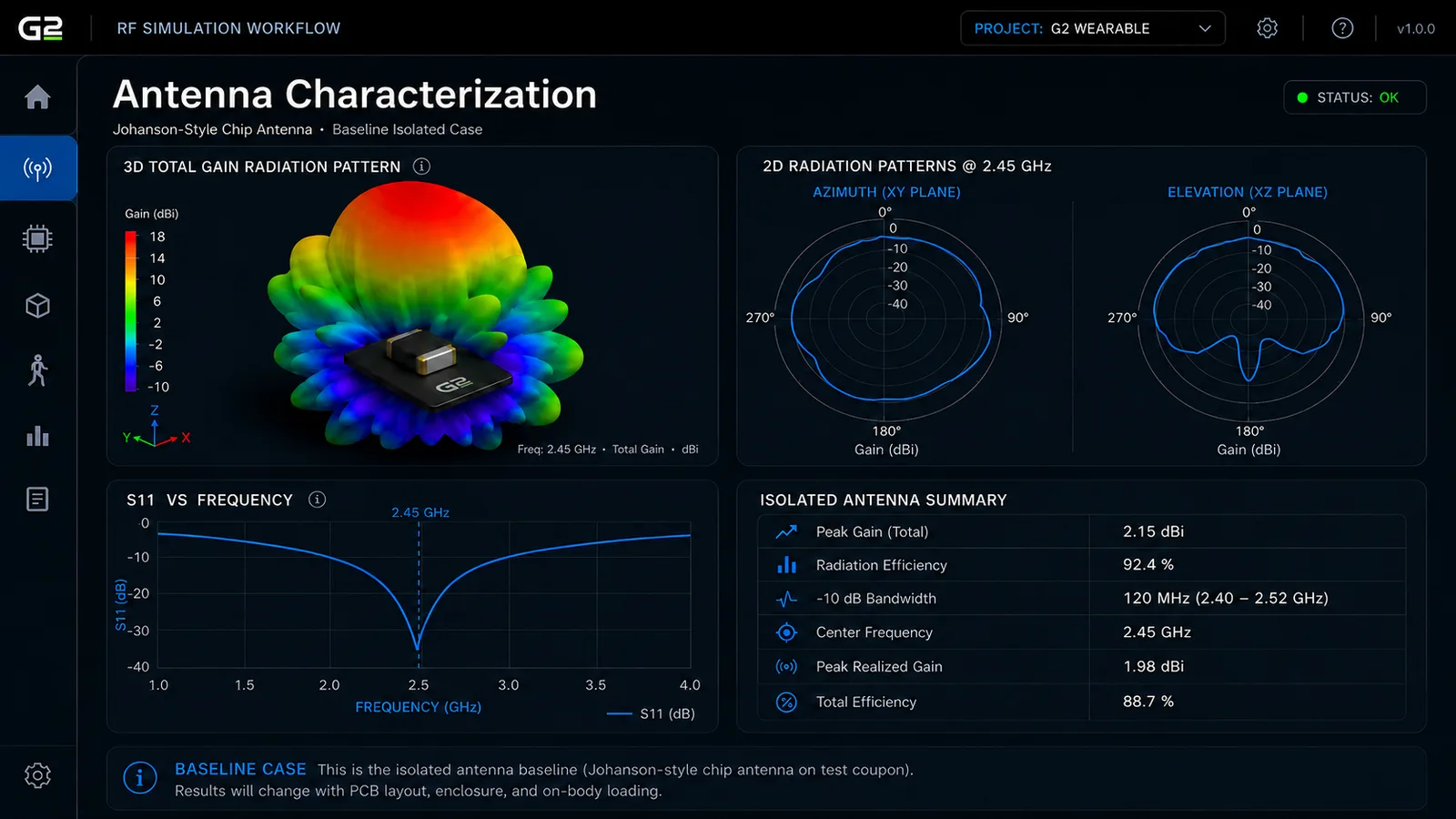
The antenna-only simulation establishes the reference case. The goal is to understand the idealized behavior of the antenna before the surrounding system disturbs it: the 3D radiation pattern, S-parameters, resonant frequency, impedance matching, bandwidth, peak gain, and radiation efficiency.

This is the ceiling. It is the best the antenna can do before the board, the enclosure, and the body enter the picture.

Antenna characterization, isolated antenna baseline
FIG 01Antenna Characterization · Isolated Antenna · Baseline Case

NoteActual outputs reflect the specific antenna geometry and target frequency band of the device being designed.

02 /Device Integration — Board and Enclosure
PCB, components, and enclosure reshape the antenna's behavior once integrated.

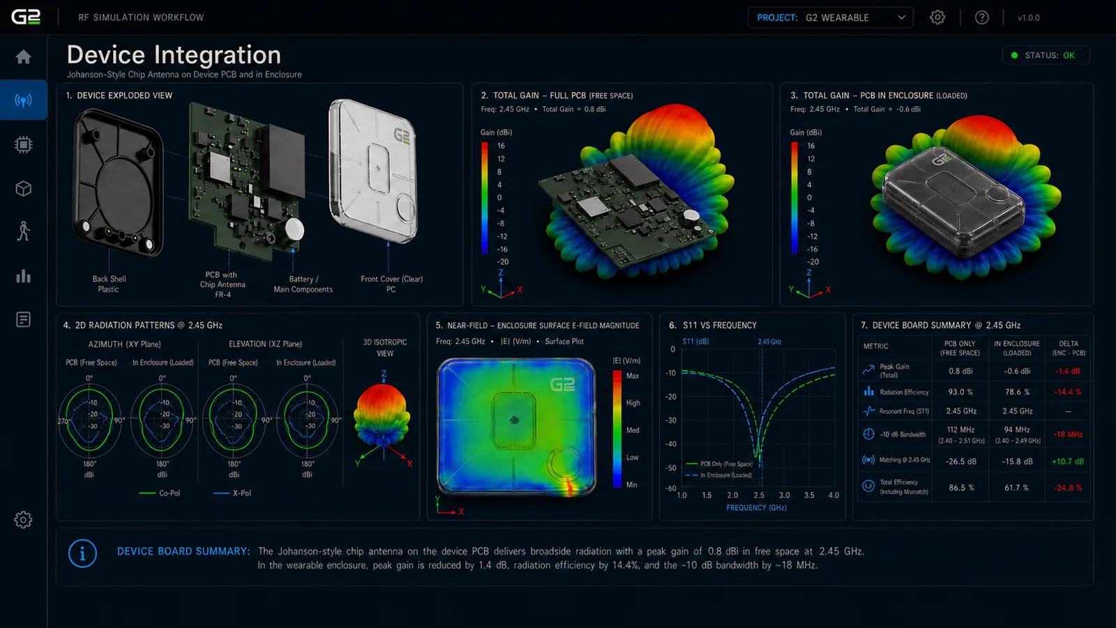
Once the antenna is placed on the full PCB, the simulation becomes more realistic. A chip antenna depends heavily on ground plane geometry, edge placement, clearance regions, nearby components, matching network, and board dimensions. This stage evaluates antenna interaction with the PCB ground, detuning from nearby components, radiation pattern distortion, board-level current distribution, and changes in S11 and bandwidth.

The enclosure simulation adds the mechanical package. Even a plastic enclosure can detune the antenna, shift resonance, reduce bandwidth, and distort the field. This is where electrical and mechanical design begin to converge, and where a layout that is mechanically convenient often turns out to be RF costly.

Device integration, chip antenna on PCB and enclosure loaded
FIG 02Device Integration · Chip Antenna on PCB · Enclosure Loaded

NoteActual outputs include comparison of free-space, PCB-integrated, and enclosure-loaded performance deltas for the specific device being designed.

03 /Device on the Human Body
Body loading, absorption, and placement-dependent performance.

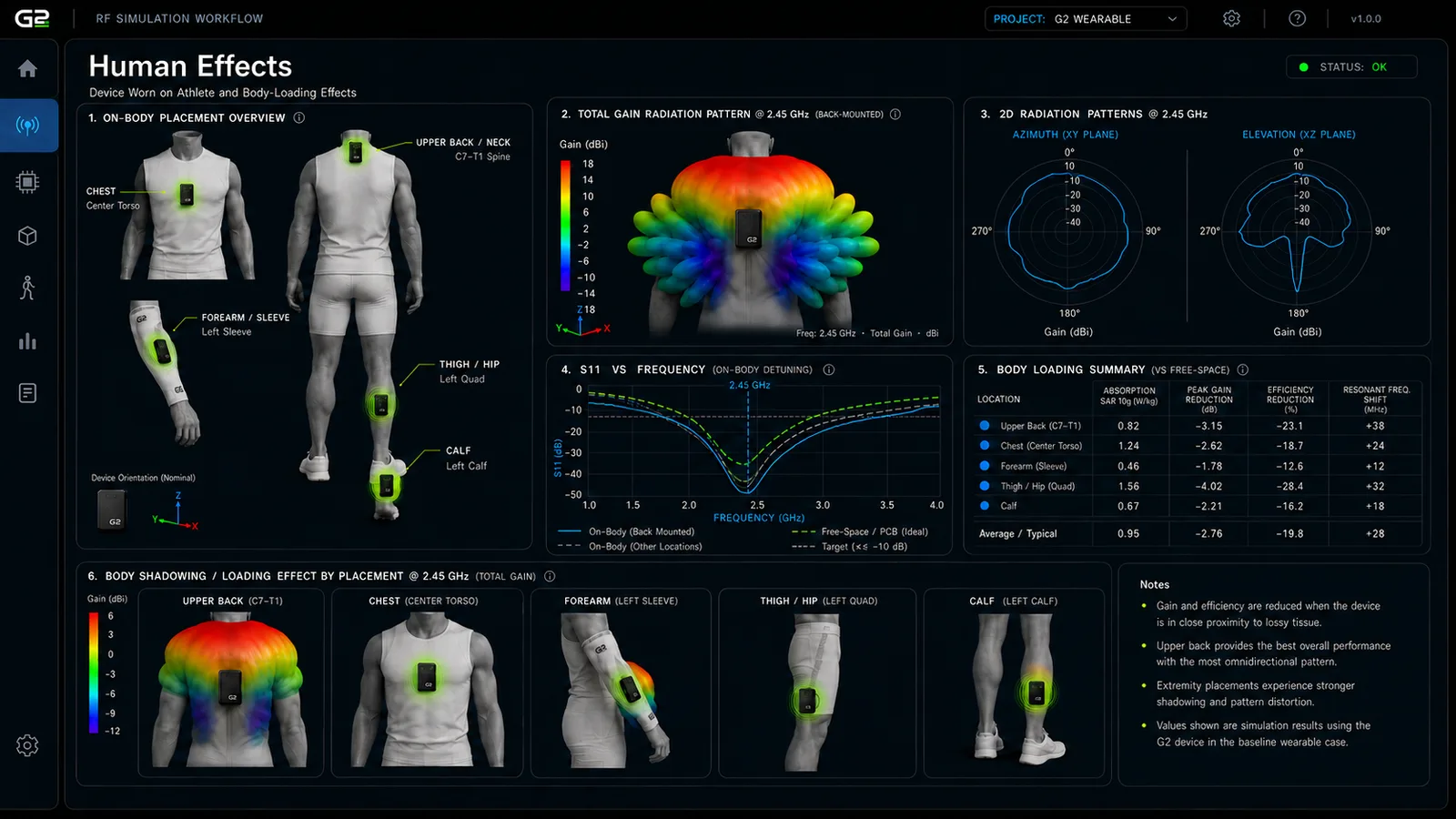
For sports wearables and body-worn sensors, on-body simulation is essential. The body changes antenna behavior because tissue absorbs electromagnetic energy and alters the antenna's near-field environment. The body can also block or shadow the signal depending on sensor placement and athlete orientation.

Sensor location becomes a design variable. A device on the upper back may behave differently from one on the chest, arm, thigh, or calf. A placement that is mechanically convenient may not be RF optimal. This stage evaluates body loading, absorption, placement-dependent performance, body shadowing, radiation pattern distortion, efficiency degradation, and resonant frequency shift. It is where simulation begins to connect directly to field performance.

Human effects, on-body placement and body loading
FIG 03Human Effects · On-Body Placement · Body Loading Summary

NoteActual outputs compare efficiency, gain reduction, and resonant frequency shift across the specific body placement options and phantom configurations being modeled.

04 /Downlink — Stadium Coverage to the Device
Venue infrastructure coverage to the wearable across the operating field.

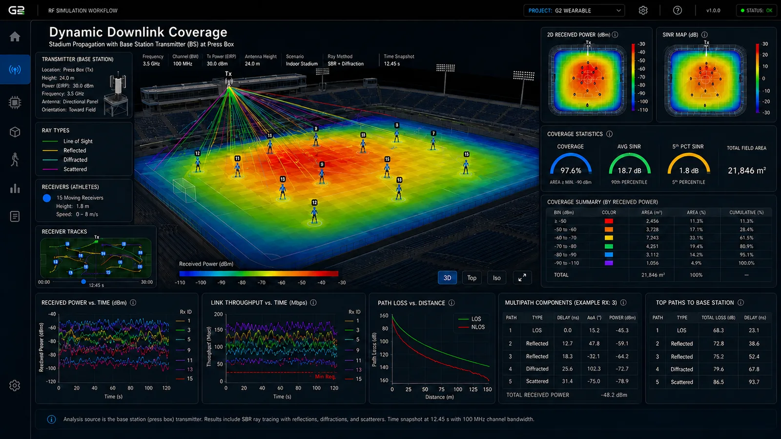
The base station as source case shows how well the field is covered by the receiver infrastructure, including where coverage is strong, where weak regions exist, and whether access points are positioned effectively. This is the planning view for the venue side of the deployment.

The simulation evaluates received power across the venue, SINR, multipath, line-of-sight and non-line-of-sight behavior, access point coverage, and link stability over time.

Dynamic downlink coverage, base station source, stadium propagation
FIG 04Dynamic Downlink Coverage · Base Station Source · Stadium Propagation

NoteActual outputs show received power, SINR maps, and coverage statistics calibrated to the field geometry, AP placement, and frequency plan of the venue being modeled.

05 /Uplink — Player-Worn Sensor to Network
The operationally relevant case for sensing networks, since data flows from athlete to network.

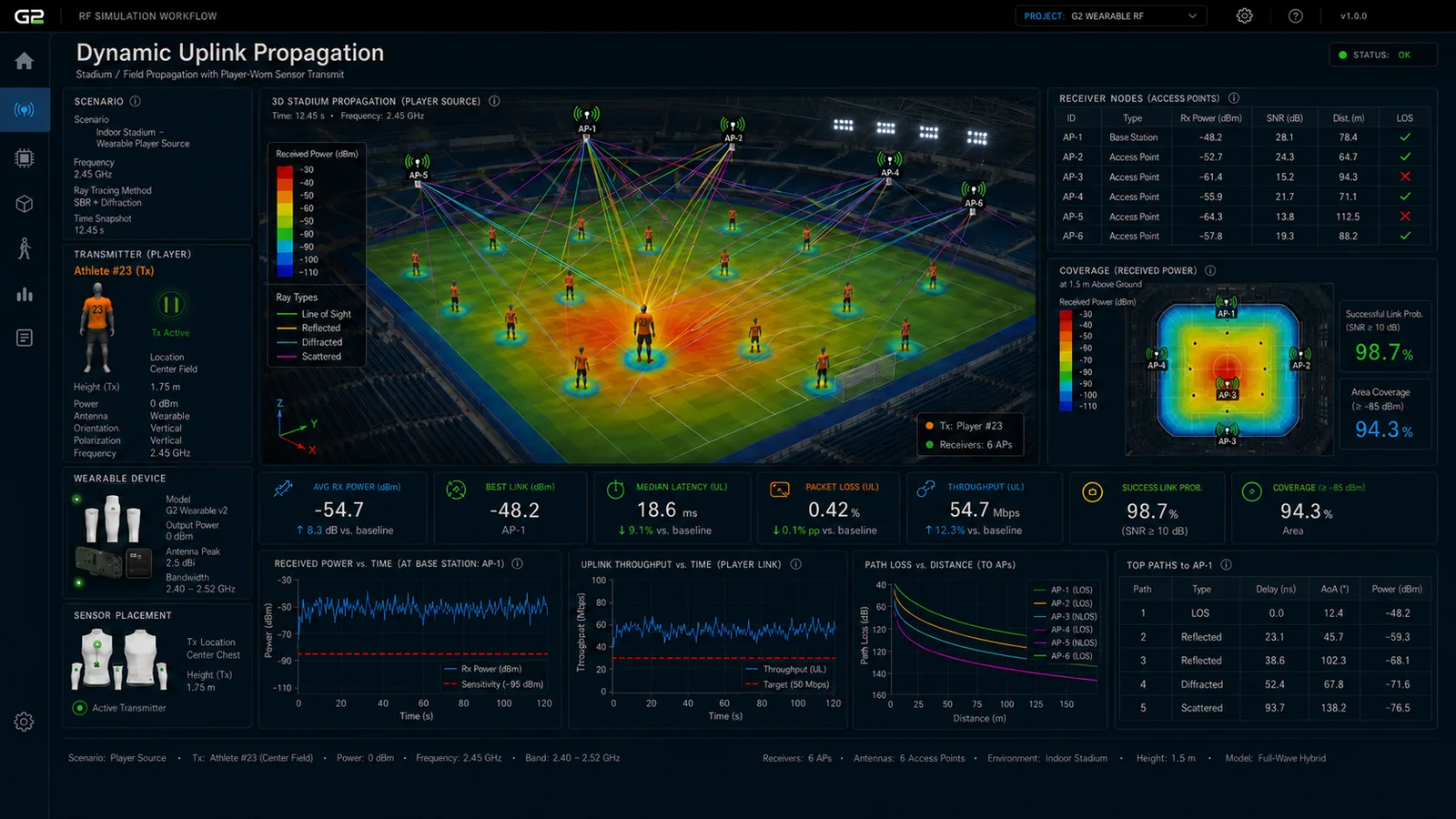
The player or device as source shows what happens when the wearable itself transmits. This is the more operationally relevant uplink case, since many sensors send data from the athlete to the network. Downlink and uplink are not always symmetric in practice.

The simulation evaluates player-to-AP link performance, path loss versus distance, multipath breakdown, link success probability, contention behavior, and the network's ability to sustain reporting cadence under crowd loading and dynamic athlete motion.

Dynamic uplink propagation, player-worn sensor source, multi-AP links
FIG 05Dynamic Uplink Propagation · Player-Worn Sensor Source · Multi-AP Links

NoteActual outputs show player-to-AP link performance, path loss vs. distance, multipath breakdown, and link success probability for the sensor configuration and venue being modeled.

From idealized device to fielded product

The simulation stages feed a small set of consequential decisions. The outcomes below are what a product team and venue operator carry into design freeze, into manufacturing, and into long-term venue deployment.

01 /Faster Product Cycles
Fewer board respins, less wasted prototype cost.

Antenna, board, and enclosure integration are modeled against on-body and on-venue loading before the first board is fabricated. Issues that would normally surface during integration, such as detuning from nearby components, field degradation under realistic loading, and multipath performance in the intended environment, are caught in simulation. Each respin avoided is weeks of cycle time recovered and a meaningful prototype budget freed for the parts of the product that genuinely benefit from iteration.

02 /Defensible Performance Claims
Datasheet specs grounded in modeled operating conditions.

Performance numbers in marketing and customer-facing material are grounded in modeled operating conditions, not in bench measurements that overstate real-world behavior. Specs are defensible against customer measurement, competitive analysis, and regulatory scrutiny because the operating envelope used to derive them was explicit. The product's reputation for matching its specifications becomes a competitive asset rather than a liability.

03 /Field Reliability Under Deployment Conditions
Test the venue before you ship to the venue.

Stadium, arena, training-field, and indoor-venue performance is modeled before the product is deployed at customer events. RF behavior under high device density, body loading from moving athletes or staff, and the specific multipath signatures of the deployment environment are evaluated in simulation rather than discovered during a championship event when stakes are at their highest.

04 /Multi-Device Coordination
Model the network before you build the network.

Many wearables in one venue interact in ways that single-device testing cannot expose: contention, interference, handoff stability, gateway loading. Simulation evaluates the deployed network across multiple devices, multiple access points, and the actual venue, and produces a configuration that can be deployed with confidence. Failure modes that would have required field fire-fighting are designed out before they manifest.

Where simulation does not solve the problem alone

Simulation does not replace bench validation, on-body testing across a real cohort, or live venue commissioning. The boundaries below are explicit so the deliverable is read accurately.

01 /Body and Posture Are Bounded by the Phantom Set
Human variability exceeds what any phantom catalog represents.

The simulation evaluates antenna behavior against a defined set of body phantoms and postures. Real athletes vary in size, muscle composition, hydration, sweat, and movement pattern. Edge cases including extreme body types, unusual placement on athletes outside the modeled set, and dynamic motion that exceeds the simulated postures are not fully predicted. Bench and on-body validation remain the way to close that gap before high-volume deployment.

02 /Venue Variability Is Bounded
Each venue is its own RF environment.

Performance is modeled against representative venues: a defined stadium geometry, a defined practice facility, a typical indoor arena. Different venues introduce different reflection profiles, different crowd loading, and different ambient RF noise. A configuration validated at one venue is a starting point, not a final answer, for a different one. Site survey remains a useful step when expanding to a new class of venue.

03 /Unknown Interference Sources Are Out of Scope
The model accounts for known emitters, not unidentified ones.

Interference simulation is bounded by what is known. The model can include planned venue Wi-Fi, broadcast infrastructure, documented incumbent emitters, and previously observed interference. It cannot foresee unknown interferers, transient emitters from broadcasters and crews, or new RF sources installed by the venue between events. Spectrum surveys during venue commissioning and post-deployment telemetry are the way to identify them, after which they can be incorporated into subsequent simulation runs.

Integrating Simulation into the Wearable Product Cycle

Simulation is integrated at the wearable device planning layer, before antenna and enclosure designs are frozen or venue rollouts are committed. Each engagement begins with a scoping call to define the operating envelope: device class, antenna geometry, enclosure constraints, target user body and posture, target venues, frequency band, regulatory profile, and the launch deadlines the deliverable must support.

Antenna and enclosure geometry, on-body conditions, and venue propagation context are then captured as a working model, and the simulation stages run against the actual deployment cases the product expects to face. Deliverables include antenna characterization in isolation, antenna-on-board performance analysis, enclosure-integrated radiation patterns, on-body human-effects evaluation, site and field propagation predictions, multi-device interference modeling, and a written brief that documents the analysis for the product team, certification bodies, and venue operators.

As the device ships across product cycles and venue deployments, the planning record grows. Post-deployment telemetry from venue performance and user feedback informs the next round of design and planning, and the simulation library becomes an internal asset that the product team carries from one generation to the next.

Designing a Wearable or a Venue Network?

For sports technology companies, wearable product teams, and venue operators planning high-density wireless deployments, we bring layered RF simulation across antenna, device, body, and venue, so design freeze and network rollout are evidence-backed rather than discovered in the field.