Residential Simulation

Residential Drone Detection Planning

A planning engagement for residential drone-detection deployments at high-value estates. Simulation is one stage of the workflow, used to select the right sensor architecture, plan placement against the property's actual geometry and vegetation, surface low-altitude ingress paths that bypass coverage, and tune alerting and tracking continuity before any hardware is mounted.

A different airspace-awareness problem than airports

High-value residential estates face a different airspace-awareness problem than airports, industrial sites, or commercial campuses. The concern is not simply whether a drone can be seen somewhere over the property. The concern is whether the estate can detect, classify, track, and respond to low-altitude drone activity early enough to protect privacy, preserve situational awareness, and support an appropriate security response.

The operational environment is unusually complex. Dense landscaping, multi-structure layouts, dock infrastructure, guest houses, smart-home systems, perimeter lighting, neighboring estates, shoreline exposure, and low-altitude approach routes all shape what sensors can see and how reliably they can track a drone. A drone may approach from over the ocean, along a waterway, across neighboring properties, or through tree-lined corridors that shield it from direct visibility until it is already near the home.

A useful simulation does more than produce a generic coverage map. It builds from physical estate geometry upward into the full operational airspace environment, evaluates how terrain, vegetation, structures, wireless infrastructure, and sensor placement interact, and shows how distributed sensors support continuous tracking, where blind spots remain, and how field telemetry can refine the model after deployment.
Residential drone detection is easy to oversimplify

It is tempting to start with a sensor datasheet, a notional range figure, or a rough coverage circle and assume the property is protected. In practice, that approach misses the real causes of underperformance. A residential estate is a cluttered, layered, and changing environment. Palm canopies, specimen trees, perimeter hedges, detached structures, pools, hardscape walls, rooftop equipment, dock features, neighboring homes, and water reflections all influence visibility. Even when the property seems open, sensors may lose low-altitude visibility near tree lines, rooflines, or guest-house courtyards. A drone can exploit those gaps.

Each layer of the simulation adds a different source of operational reality. Estate geometry establishes what physically exists. Terrain, landscaping, and structures define occlusion. Sensor placement determines whether likely ingress routes are actually observable. RF and interference analysis determines whether the sensing system performs reliably in the real estate environment. Ingress-path simulation converts static coverage into actual detection opportunity. Tracking continuity and alerting determine whether the system is operationally useful. Telemetry calibration turns the model into a living operational tool rather than a one-time planning exercise.

Skipping a layer may still produce a polished output, but it will not produce a trustworthy one.

Eight stages. Each one answering a different question.

The simulation moves through the estate from physical scene to operational alerting. Each stage below produces a specific artifact and answers a specific operational question. Figures shown are representative. Actual outputs are produced against the specific estate geometry, sensor inventory, and operating environment being modeled.

01 /Estate Geometry and Digital Twin Construction
Physical baseline before RF and sensor results are trusted.

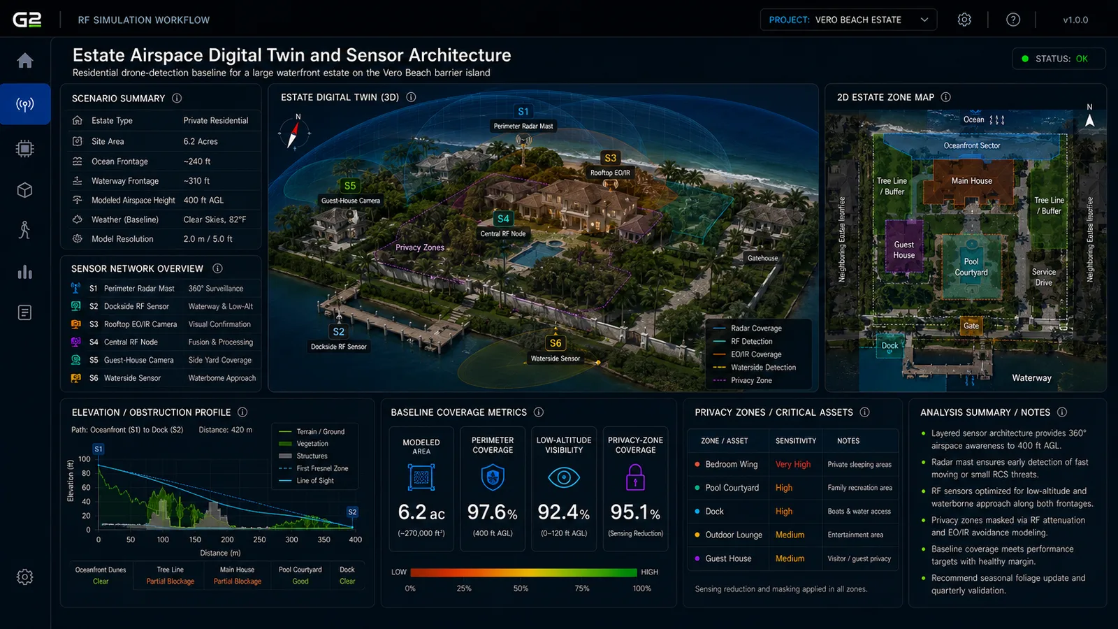
The first layer builds the estate as a physical environment. This includes the main residence, guest houses, walls, courtyards, landscaping, dock areas, rooflines, trees, service drives, and neighboring structures that materially affect visibility.

In a residential setting, small details matter. A roof parapet, tree cluster, or guest-house corner may create a local blind spot large enough to delay detection of a low-flying drone. If this layer is skipped, later detection maps may overestimate performance: a sensor that appears to cover the property in a simple open-site model may in reality lose sight behind a tree canopy, courtyard wall, or detached building.

Estate airspace digital twin and sensor architecture
FIG 01Estate Geometry & Digital Twin Construction · 3D Estate Digital Twin · Physical Baseline Before RF and Sensor Results Are Trusted

NoteActual outputs reflect the specific estate geometry, structures, tree lines, and sensor mounting positions being modeled.

03 /Baseline RF Visibility and Coverage Modeling
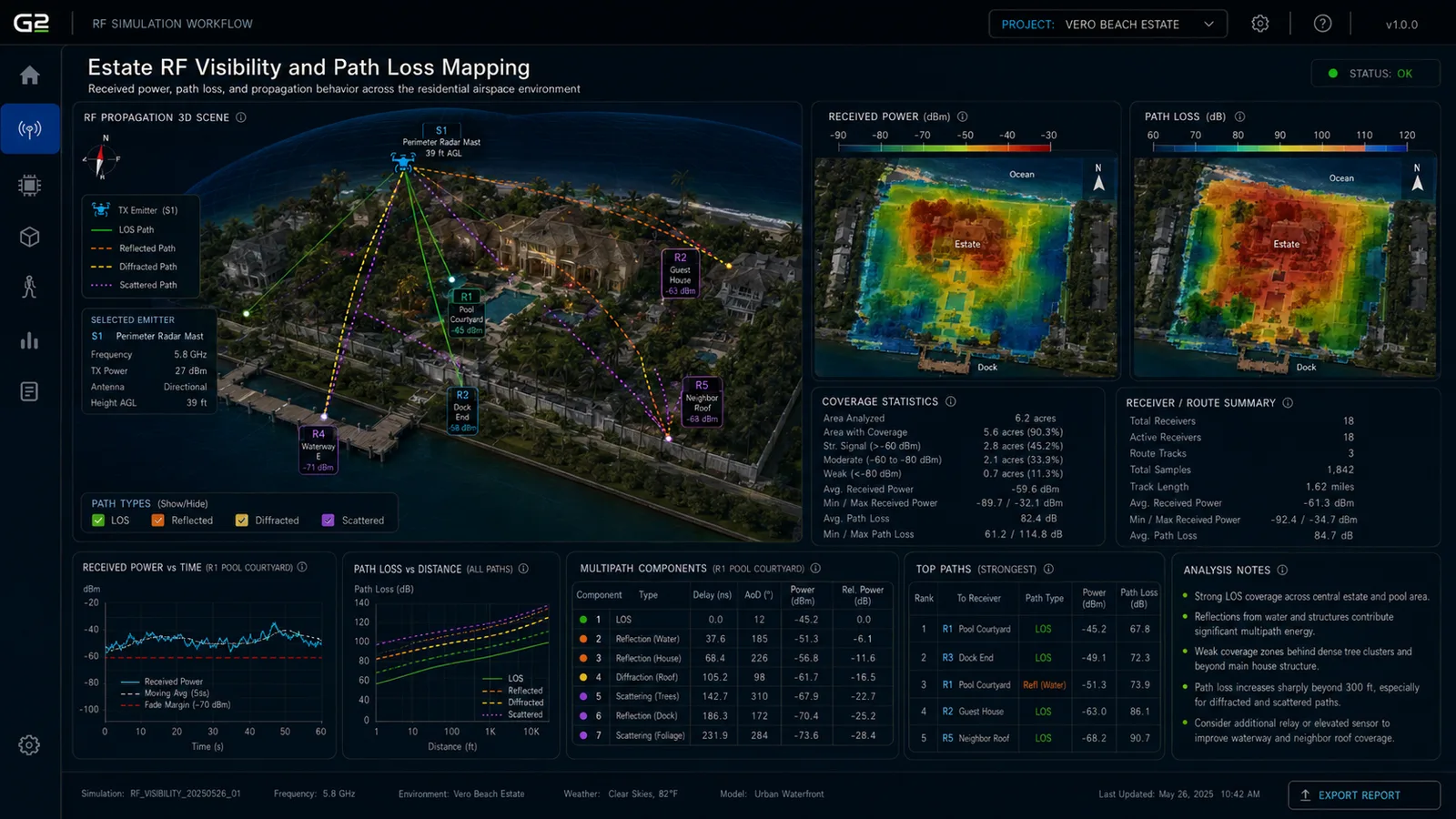
Received power, path loss, and line-of-sight across the estate airspace.

This layer evaluates received power, path loss, and basic RF visibility across the estate environment. For drone-detection systems using RF sensing, wireless backhaul, or integrated detection infrastructure, this establishes the baseline performance envelope.

Estate properties are filled with RF activity: Wi-Fi, mesh systems, cameras, smart-home hubs, access-control infrastructure, marine electronics, guest devices, and neighboring wireless sources. Even if the drone-detection system is not purely RF-based, the broader RF environment affects coexistence, backhaul, and sensor coordination. If this layer is skipped, the system may appear functionally sound but prove unreliable when deployed alongside the real estate's wireless environment.

Baseline RF visibility and coverage modeling
FIG 02Baseline RF Visibility & Coverage Modeling · Received Power · Path Loss · Line-of-Sight Across the Estate Airspace

NoteActual outputs reflect site-specific propagation, foliage attenuation, and structure shadowing for the estate being modeled.

04 /Interference and SINR Analysis
Spectrum coexistence, detection SINR, estate wireless loading.

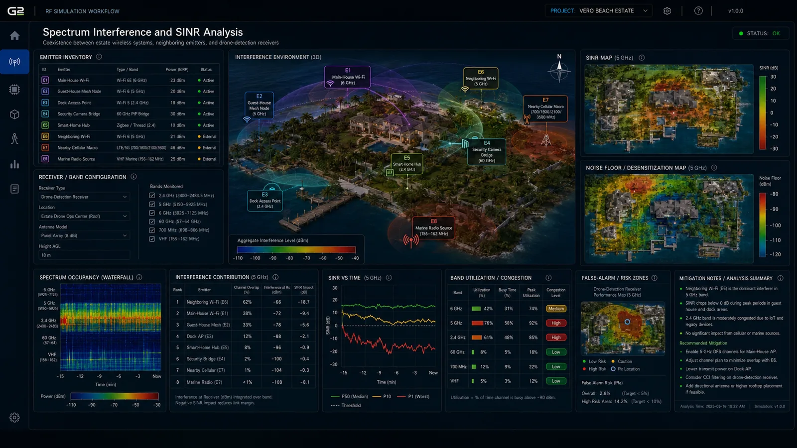
This layer evaluates SINR and interference conditions at drone-detection receivers and supporting wireless systems. It examines interactions among estate wireless infrastructure, smart-home systems, neighboring RF sources, marine electronics, and any distributed sensing hardware.

A high-end estate typically has dense embedded technology. Interference may not fully break the system, but it can reduce receiver quality, increase false alarms, or weaken detection reliability at exactly the wrong locations. If this layer is skipped, system design may depend on idealized assumptions and understate coexistence risk.

Interference and SINR analysis
FIG 03Interference & SINR Analysis · Spectrum Coexistence · Detection SINR · Estate Wireless Loading

NoteActual outputs reflect the spectrum environment, neighboring emitters, and detection sensor configuration at the site being modeled.

05 /Sensor Placement and Overlap Optimization
Coverage overlap, blind-spot analysis, low-altitude detection assurance.

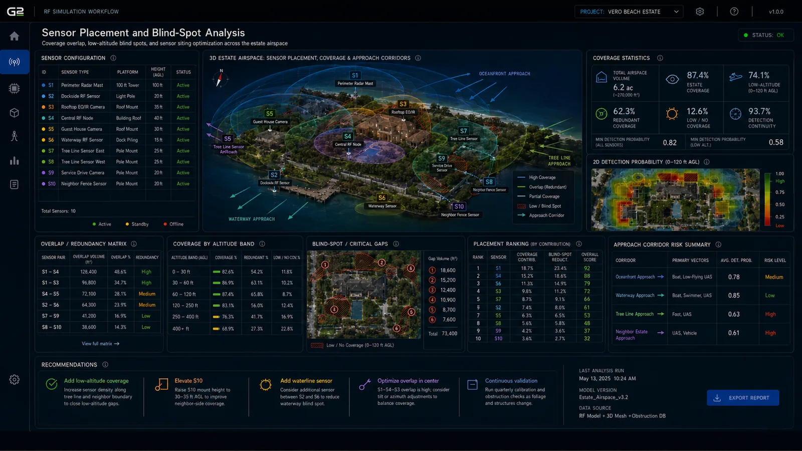
This layer studies the placement of radar, RF sensing nodes, EO/IR cameras, and supporting infrastructure across the estate. Residential drone detection depends on placement far more than on nominal device range. A sensor installed on a beautiful but convenient rooftop may provide worse low-altitude coverage than one mounted on a slightly less central mast or guest structure. The right placement can also reduce the need for unnecessary extra hardware.

Likely candidate placements include main-house roofline or parapet positions, guest-house roof mounts, dockside or waterside poles, perimeter mast locations, gatehouse or service-building mounts, elevated landscape-integrated poles, and central architectural vantage points where they exist. If this layer is skipped, installation decisions drift toward convenience rather than actual operational performance.

Sensor placement and overlap optimization
FIG 04Sensor Placement & Overlap Optimization · Coverage Overlap · Blind-Spot Analysis · Low-Altitude Detection Assurance

NoteActual outputs reflect the specific sensor count, mounting heights, and overlap requirements selected for the deployment being modeled.

07 /Drone Ingress-Path Modeling
First-detection timing, approach geometry, response-window analysis.

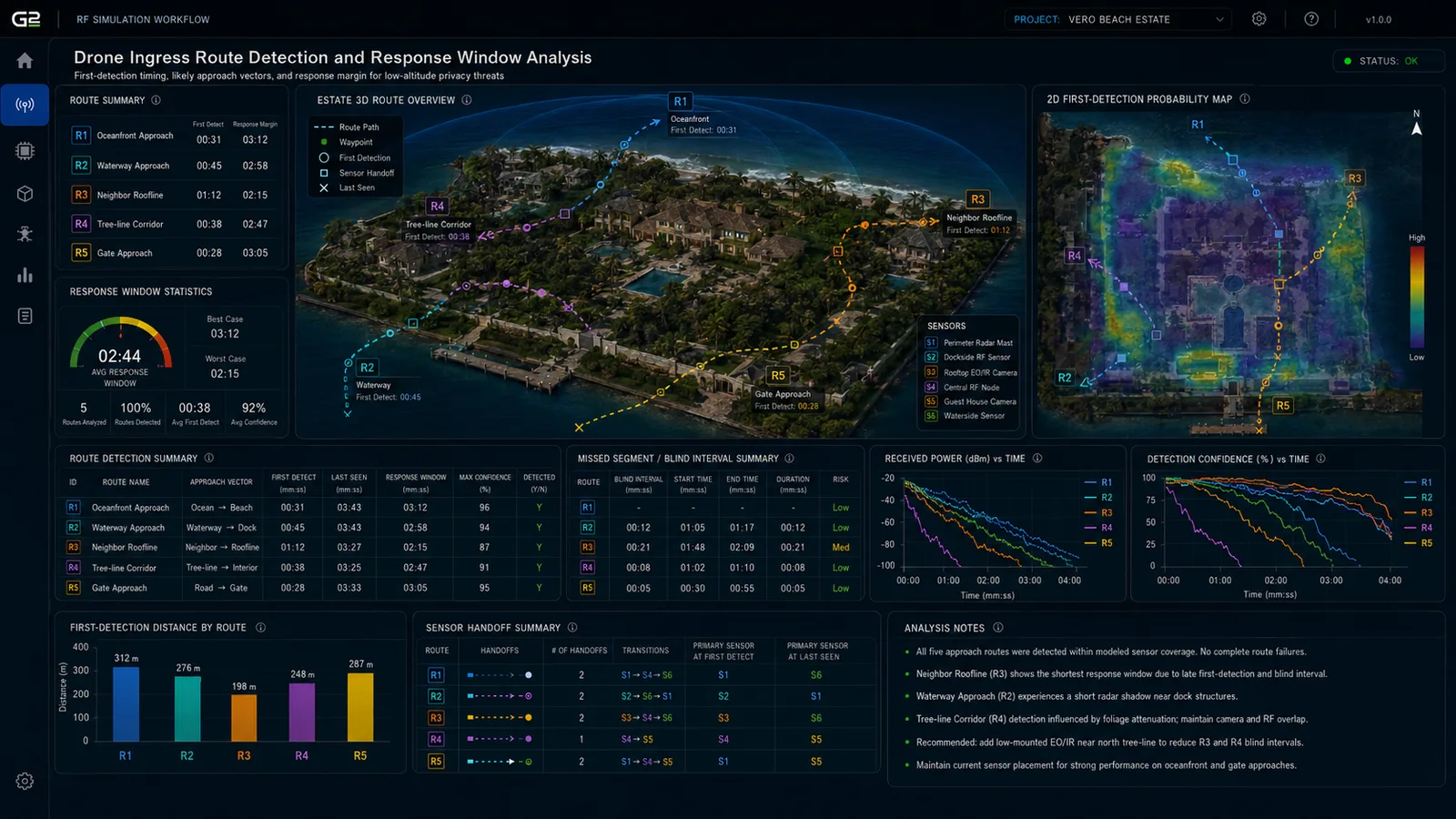
This is one of the most important layers. The model evaluates likely drone approach routes into and around the estate, including oceanfront low-altitude approach, waterway or dockside approach, neighboring-estate roofline approach, tree-line corridor ingress, perimeter fence or gate approach, overhead hover or loiter path, and courtyard or rear-garden penetration route.

Static coverage maps do not show whether a drone is detected early enough to matter. A system may technically cover much of the property but still miss the most privacy-sensitive ingress path until the drone is already near an outdoor living area, bedroom wing, or dock. If this layer is skipped, the estate may believe it has broad detection coverage while still remaining vulnerable to the most realistic approach paths.

Drone ingress-path modeling and response-window analysis
FIG 05Drone Ingress-Path Modeling · First-Detection Timing · Approach Geometry · Response-Window Analysis

NoteActual outputs reflect realistic ingress vectors, drone classes, and approach altitudes modeled against the estate being studied.

08 /Airspace Tracking Continuity
Dynamic track maintenance through structure and tree-line transitions.

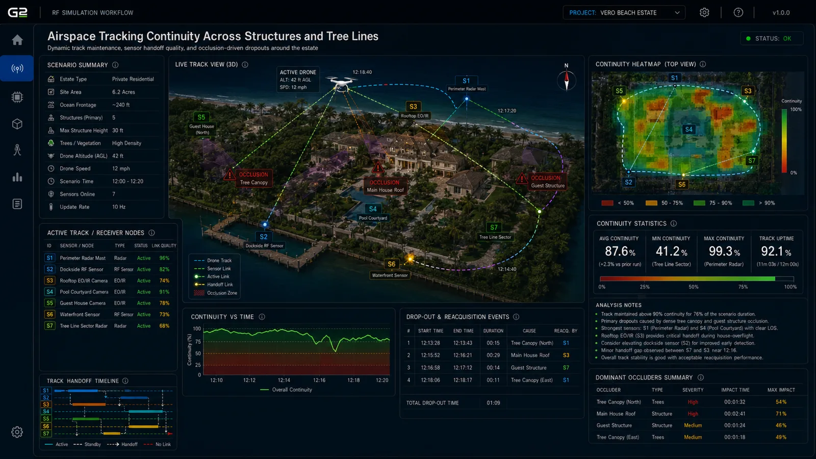
This layer evaluates how well the system maintains track continuity as a drone moves dynamically around the property. Residential properties create fragmented observation geometry. A drone may be visible from a waterside sensor, then masked behind a roofline, then reacquired by a tree-line camera, then partially lost again near a guest house. A useful system must manage that continuity.

If this layer is skipped, the system may show isolated detections without delivering a stable operational picture. The stage answers how many sensors are needed for continuity rather than simple detection, where sensor overlap is most valuable, and whether tracking quality degrades near privacy-sensitive areas.

Airspace tracking continuity across structures and tree lines
FIG 06Airspace Tracking Continuity · Dynamic Track Maintenance · Structure and Tree-Line Transitions

NoteActual outputs reflect track continuity behavior through the specific structural and vegetation handoff zones of the estate being modeled.

09 /Operational Alerting and Escalation Logic
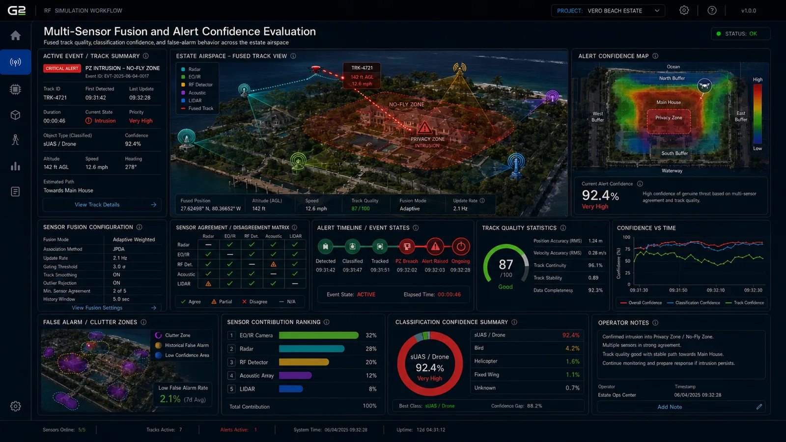
Fused track confidence, classification, alert quality evaluation.

Detection is not the end goal. This layer models how alerts are generated, escalated, and acted upon. An estate needs operational clarity, not raw data. Not every detection should trigger the same response. A drone over the ocean at standoff range is different from a drone descending near the bedroom wing or hovering near the dock at night.

The alert model examines initial awareness alerts, sector-based escalation, loitering or persistent-presence detection, no-fly-zone or privacy-zone intrusion, multi-sensor confirmation thresholds, and response coordination across estate staff or security partners. If this layer is skipped, the estate may receive either too many alerts or too little meaningful guidance.

Operational alerting and escalation logic
FIG 07Operational Alerting & Escalation Logic · Fused Track Confidence · Classification · Alert Quality Evaluation

NoteActual outputs reflect the fusion logic, classification rules, and escalation policies defined for the operations team being supported.

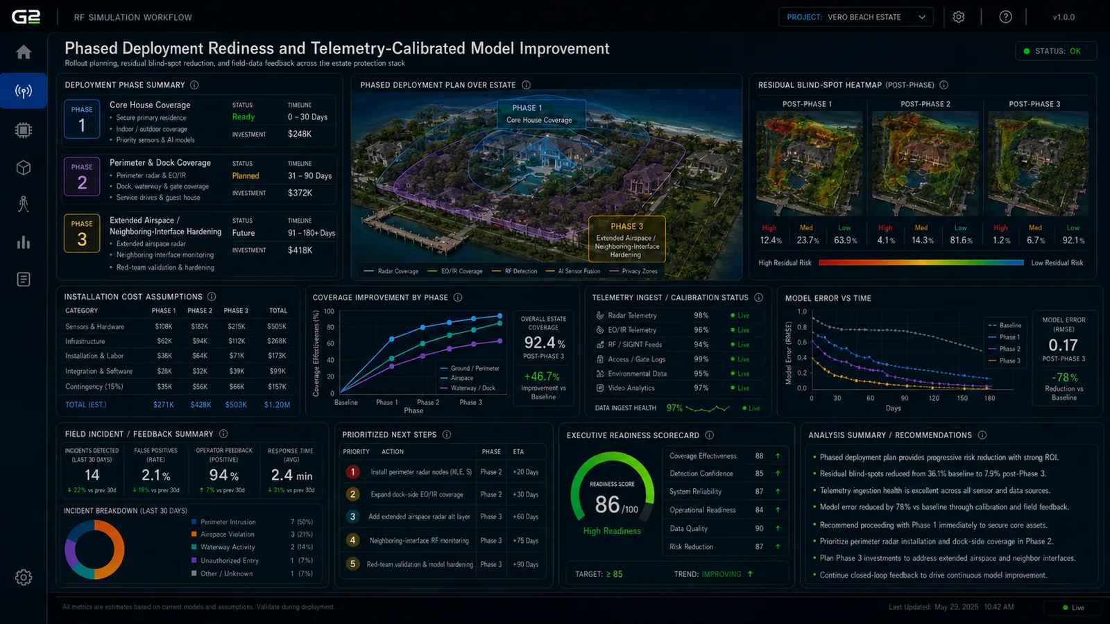
10 /Post-Deployment Telemetry and Model Calibration
Rollout planning and telemetry-calibrated model improvement.

The final layer uses field data to refine the simulation after deployment. Every estate environment contains details that are difficult to predict perfectly: seasonal vegetation changes, smart-home RF activity, neighboring emissions, and the actual signatures of drones that show up over the property. Useful calibration inputs include received-signal measurements, false-alert logs, sensor health and uptime data, track histories, observed drone events, and time-of-day patterns.

If this layer is skipped, the model remains static and gradually diverges from reality. With it, threshold retuning, sensor relocation or addition, and classification and alert improvements are all driven by evidence rather than guesswork.

Post-deployment telemetry and model calibration
FIG 08Post-Deployment Telemetry & Model Calibration · Rollout Planning · Telemetry-Calibrated Model Improvement

NoteActual outputs reflect the calibration cadence, telemetry sources, and rollout schedule established for the site being supported.

Coverage you can defend, response you can trust

The simulation stages feed a small set of consequential decisions. The outcomes below are what an estate carries into procurement, into installation, and into long-term operation. They are the deliverables that justify the planning engagement.

01 /System Selection
Choose the right sensor architecture for this estate, not a generic kit.

Radar, RF sensing, EO/IR, and acoustic systems each behave differently against a residential property's vegetation, structures, water frontage, and existing wireless environment. The simulation surfaces which modalities the estate actually needs, where each performs best, and where overlap is required. Procurement decisions are anchored to evidence rather than vendor data sheets, and the kit ordered matches the property's operational reality.

02 /Deployment Planning
Where sensors mount, in what sequence, and how they integrate with existing estate systems.

Sensor placement is ranked against the obstruction model, ingress-path analysis, and estate geometry. The deployment plan covers mounting positions on main residence rooflines, guest structures, perimeter masts, and dockside or waterside poles, along with integration with existing access control, security, and smart-home infrastructure. Phased install sequencing identifies which positions unlock the most coverage early.

03 /Detection Coverage Against the Actual Estate
The model knows what the estate looks like.

Detection coverage is evaluated against the actual estate, including landscaping, structures, dock features, neighboring properties, water features, and low-altitude ingress corridors, rather than against a notional perimeter. Sensor placements that look adequate in a flat-map view but lose coverage behind a palm canopy or a guest-house roof are caught before installation. The estate's actual operational airspace, not a generic one, becomes the design reference.

04 /Response Time and Alert Quality
Alerting tuned to the estate, not to the datasheet.

Alert thresholds and escalation rules are tuned against the estate's actual ingress paths and against the response capability that backs them. Nuisance alarms from birds, neighboring drones, or routine activity at the property line decrease. Real incidents trigger response that has the time it needs to be effective. The system becomes operationally trusted rather than increasingly ignored.

05 /Insurance and Liability Posture
Documented coverage supports underwriting and incident defense.

Documented analysis of detection coverage against the property's actual ingress geometry supports underwriting conversations and incident-defense documentation. An estate that can show what its airspace-awareness system is designed to do, and where it is not designed to do it, is in a different position than one where the system was installed without analysis.

06 /Upgrade Planning
Capital decisions backed by the model.

As the drone threat landscape evolves with new vehicle types, new ingress patterns, and new use cases at residential properties, the simulation evolves with it. Capital decisions about additional sensors, additional response infrastructure, or upgrades to existing systems are model-backed rather than vendor-driven.

Where simulation does not solve the problem alone

Simulation does not replace owner protocol, response capability, or live spectrum surveys. The boundaries below are explicit so the deliverable is read accurately.

01 /Detection Coverage Does Not Equal Response
Coverage tells the system where a drone could appear. Response is a separate problem.

Detection coverage shows where the sensor architecture can observe a drone over the estate and its surrounding airspace. Whether the drone is interrupted, identified, neutralized, or simply logged depends on response capability, alerting workflows, on-property staffing, owner protocol, and external coordination with law enforcement, none of which are inside the RF simulation. A well-modeled sensor footprint that lands at an estate without a tuned response plan can still leave the property exposed.

02 /Adversarial and Atypical Drones Are Not Modeled
The simulation assumes drones behave like the ones we have characterized.

Detection performance is evaluated against drone signatures that have been measured or specified. Adversarial drones that intentionally fly silent, modulate their RF emissions to avoid detection, operate near or below the receiver noise floor, or use atypical airframes are outside the model. New drone types, especially purpose-built or modified airframes, may have signatures the model does not yet represent.

03 /Unknown Local Interference Sources Are Out of Scope
The model accounts for known emitters, not unidentified ones.

Interference simulation is bounded by what is known. The model can include the estate's own wireless systems, documented neighbor emissions, planned marine and waterway RF, and previously observed interference at the property. It cannot foresee unknown interferers, transient emitters from passing vessels or visiting crews, or new RF sources installed by neighbors. Spectrum surveys during site survey and post-deployment telemetry are the way to identify them, after which they can be incorporated into subsequent simulation runs.

Integrating Simulation into Estate Airspace Programs

Simulation is integrated at the residential security planning layer, before sensor placement is committed or coverage is reported to the estate owner and insurer. Each engagement begins with a scoping call to define the operating envelope: estate geometry, vegetation and structure inventory, threat surface, candidate sensor positions, alerting protocol, integration with existing security infrastructure, and the privacy and liability framework the deliverable must satisfy.

Estate geometry, terrain and vegetation context, and the local RF environment are then captured as a working model, and the simulation stages run against the actual ingress and tracking cases the estate expects to face. Deliverables include the estate airspace digital twin and sensor architecture, RF visibility and path-loss mapping, spectrum interference and SINR analysis, sensor placement and blind-spot evaluation, ingress-route detection-window predictions, tracking continuity analysis, multi-sensor fusion and alert confidence evaluation, phased deployment readiness, and a written brief that documents the analysis for the estate owner, security operator, and insurance carrier.

As the estate's detection program operates across seasons and incident histories, the planning record grows. Post-deployment telemetry from detection events and sensor health informs the next round of planning, and the simulation library becomes an internal asset that the security operator carries across the property's lifecycle.

Planning Drone Detection for a Residential Property?

For estate owners, security operators, and family offices managing high-value residential properties, we bring layered simulation, RF expertise, and sensor-system design to drone-detection planning, so system selection, sensor placement, and alerting are evidence-backed before installation begins.